
In my adventures taking aircraft maintenance classes at Mount San Antonio College, I’ve learned a lot of things. Not the least of which, is how much I have to learn!
Another piece of knowledge I’m grateful for, is how to drive and set solid rivets. I’m not the best at it, but I can do it, and practice will make me better.
One thing about riveting has been indelibly etched in my brain. Rivets require precise holes to be properly fitted. So much so, that a rivet is often referred to by the drill used to make the hole it fits in.
For example, a “30” rivet is a 1/8 diameter rivet, and uses a #30 drill for it’s pilot. A “40” rivet is 3/32 in diameter, and uses a #40 drill for it’s pilot.
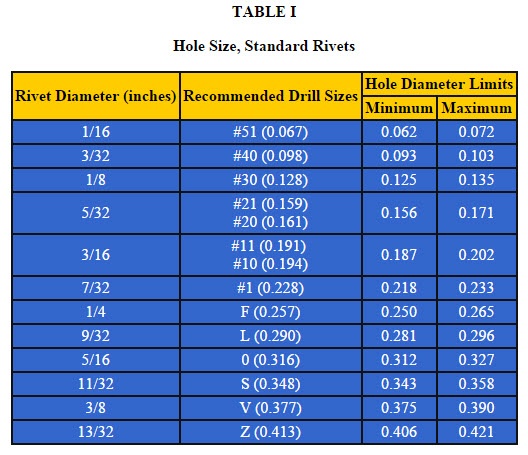
A sample of the hole size for standard Imperial Rivets from EngineersEdge
If you’re inclined to read about it in detail, you can find the specs at Engineer’s Edge here, or in the Advisory Circular AC43.13 from the FAA here (PDF, start at page 4-14)
Merging that knowledge with my Autodesk Inventor knowledge, I found myself thinking, “How can I capture that knowledge?”.
My thoughts turned to the clearance hole table, which is maintained by an Excel file named Clearance.xls, can contain the new information I wanted to add.
I thought I’d share the steps I used for adding these holes. Perhaps this is something you can use to adapt your own special clearance holes.
There are two types of clearance holes, the universal rivet, and countersunk rivet. Basically, that means I need a countersunk hole, and a straight hole. I won’t be using counterbores for rivets.
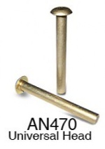
Universal Head Rivet from Aircraft Spruce
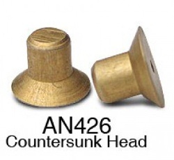
A countersunk rivet from Aircraft Spruce
So let’s get started.
The first step? Close Inventor. This will make sure that when you place a hole, you’re reading in the latest clearance table. I also ran into errors when I tried placing holes with the clearance table open. It had something to do with Excel locking the file.
Locate the clearance.xls file. It’s location can vary, but it’s set either in the Design Data location in Application Options, or Design Data in the Project. Remember that if the path is set in the Project file, it will take precedence over the Application Option setting.
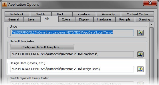
The Design Data location set in Application Options.
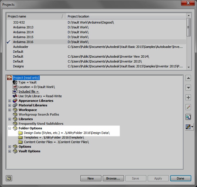
The Design Data location set in the project.
When you find the location, look for the …Design DataXLSen-US sub directory. It will have the Clearance.xls file you’re looking for.
Before doing anything else, make backup of the original Clearance.xls file. Just in case it goes horribly wrong, the backup provides a safe haven to go back to and try again.
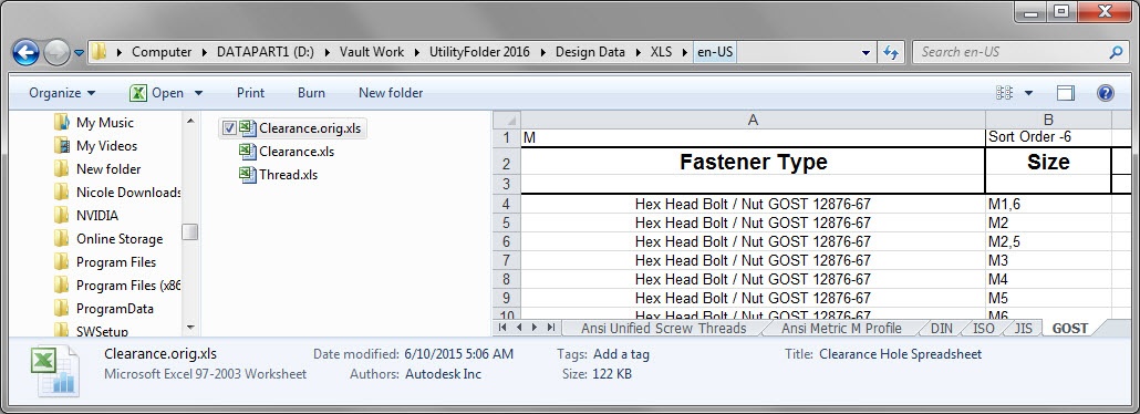
The location for Clearance.xls. Notice I’ve also got a backup Clearance.orig.xls
Next, it’s time to edit the Clearance.xls file and add in the new values.
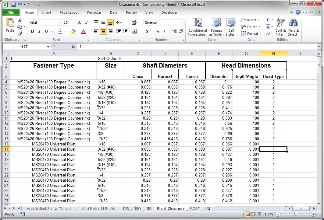
Looking at the sheet, there are several columns, and it goes without saying that each does something. Some will be more obvious than others.
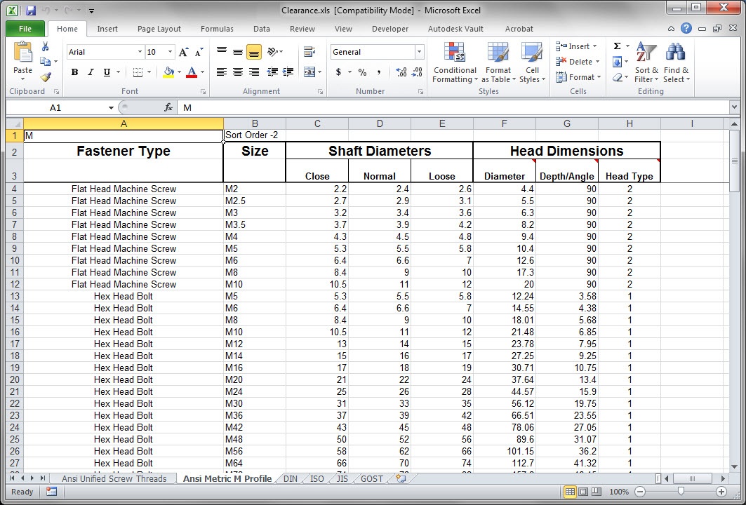
A sample of one of the charts in the Clearance.xls chart.
From left to right, here they are.
- Fastener Type – This is a description of what type of fastener you’re using the hole for. This is the value you select in the hole dialog box.
- Size – This can be called the “nominal’ name for the clearance hole. In other words, if you’re describing this fastener or clearance “in the shop” what are you asking for?
- Shaft Diameters – This includes diameters for Loose, Normal, and Close fits. Very typical diameters for many fasteners.
- Head Dimensions – This is broken down in to three columns that require clarification on their own.
- Diameter – The diameter to accommodate a fastener’s head.
- Depth/Angle – This is the depth required to clear the head, or if a countersunk fastener, the angle of the head.
- Head Type – What type of fastener this is. The number “2” designates a countersunk head. A “1” designates a ‘standard” head.
Armed with that knowledge, it’s time to setting things up!
The easiest thing I found to do is copy one of the existing sheets. It can serve as a template to create the new table.
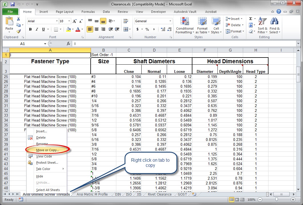
Copying the Excel table
So now the table is copied, we understand what the columns do. It’s time to start editing.
Most of this is just taking the values from the standards and copying them into the tables. But I am going to use a couple of tricks to get the table to do what I want.
For starters, rivets don’t have close, normal, or loose fits, there’s really just one proper nominal dimension. So I’m going to set the the values to close, normal, and loose to the same thing. That way, no matter which the end user chooses, they get the right one.
Also, I’m not using counterbores with my universal rivets. In order to make that “unselectable”, I’m going to set the counterbore diameter to be smaller than the shaft diameter.
Making the counterbore diameter smaller than the shaft diameter will force the counterbore to “error out” if someone tries to use it. It’s not fancy, I know, but it will work. I can always change it later too!
My creation. The rivet clearance chart for Inventor
That’s the big part, but now there’s a couple of more details left.
I’m going to set the “Sort Order” to make sure that the tab appears where I want it. This affects the order in which the table appears in the hole dialog box. Just like the name describes, 1 is first, 2 is second, etcetera, etcetera. (A guy with my haircut has to use that reference!)
I’ll also rename the sheet to something meaningful to someone using it. You know, like “Rivet Clearance”. It took me a while to come up with that one! (sarcastic grin).
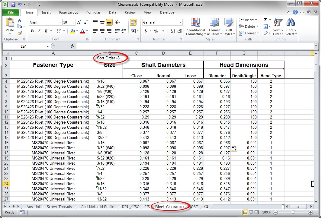
Changing the Sort Order, and renaming the table.
Once this is done, fire up Inventor, and test out your new table of date! Now you’re ready to go! You can see where the Table Name, Fastener Type, and Size appear in the hole dialog box.
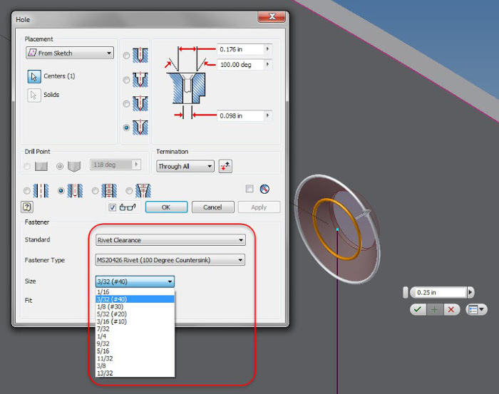
Placing the Rivet. Notice how the names (circled) correspond to the Clearance.xls table.
Now, it’s time to “serve and enjoy” your new chart. And don’t forget to make a backup of this data too! There’s nothing worse than doing it twice.
Even if you can’t use it for rivets, perhaps you can adapt this for something else!
Thanks Jonathan…..good post!
Thanks, Michael! I’ve seen so many good technicians who know that information cold. I had to capture it somehow!