Every year, the KETIV team and Autodesk Product Managers team up to provide the Autodesk community with some of the year’s most anticipated webinars, What’s New in Inventor, Vault, and AutoCAD 2021. They are all about the new features, workflows, and functionality that Autodesk has included in new releases of the software.
For myself in particular, these are some of my favorite webinars as they show the close connection and teamwork between KETIV and our friends at Autodesk. These webinars typically happen shortly after the product hits “electronic” shelves and provides the user-base with a first look at the tools they continue to use each and every day. This year has been no different even with our ever-changing surroundings and obstacles caused by working from home, as our teams have delivered individual webinars for AutoCAD, Autodesk Vault, and Autodesk Inventor respectively.
What’s New in AutoCAD, Vault, and Inventor 2021 Round-up
What’s New in AutoCAD 2021 with Thomas Stuhle
The first webinar was surrounding AutoCAD, one of the flagship product offerings at Autodesk. Some may think of AutoCAD as a dated product, as it has been in existence for close to 40 years. Autodesk has continually improved their products each year and AutoCAD is no different. Autodesk’s AutoCAD Senior Technical Specialist, Thomas Stuhle, focused a lot of his presentation around some of the improved collaboration and connectivity enhancements.
The AutoCAD web application now allows users to view and even edit drawings while on the go. Further emphasis was also placed around the existence of the Specialized Toolsets. AutoCAD comes in many different flavors, some of which are catered to specific workflows and design. These toolsets include, Mechanical, Electrical, MEP, Architecture, to name a few; all allowing users to utilize industry specific libraries and functions.
What’s New in Vault 2021 with Irvin Hayes Jr.
The second in the trio of webinars was presented by Autodesk Vault Product Manager, Irvin Hayes Jr. It’s been my personal pleasure to work with Irvin on these webinars over the past three Vault releases and see how the tool has evolved in the last few years.
The biggest game changer in Vault 2021 is the inclusion of Smart Duplicate Search and Reduction. Users can easily run a 3D geometric search for parts so there is less time wasted documenting, releasing, replacing, and managing duplicate files. This feature is worth the upgrade to 2021 alone, as we have seen it save hours by reusing correct parts and deleting unnecessary duplicates.
Other new features include unused document detection, and some updates to copy design, that make user’s lives easier through some of the most commonly utilized tools within Vault. These are just a few of the additions to the 2021 version of Vault, so make sure to view the recording below for all of the info you need.
What’s New in Inventor 2021
Last but certainly not least is Autodesk Inventor 2021. Back when we first started this annual What’s New Series, the KETIV team worked closely with Inventor Product Manager Loren Welch, and the rest of his team. Loren and his team have not only provided us with these webinars but have also given our customers the unique opportunity to influence future releases by providing feedback on pre-release versions of the software.
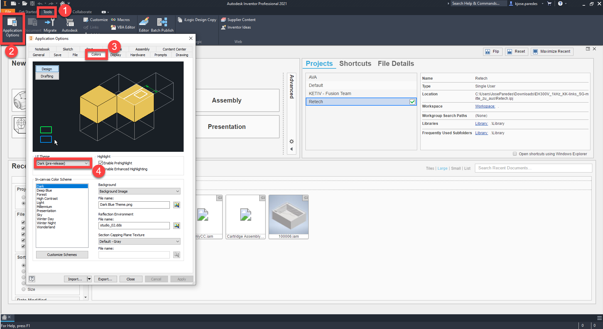
This year, Garin Gardiner took the reins on the presentation and gave us a guided tour of everything they have jam-packed into this release. Hundreds of customer-driven ideas have influenced the direction in which the development team has taken the software, and this webinar highlighted many of them. In addition to improved performance and stability, the Inventor team has completed a multi-year project in improving the overall Inventor experience with updated property panels and a brand-new dark theme.
Additionally, users are happy to have heard that Autodesk has listened to the users and have improved the workflow between Inventor and Autodesk Revit. As an increasing amount of building product manufacturers need to transfer data to and from our architectural friends, the need for a smooth workflow has become apparent. These inclusions in the software provide an easy decision for users to make the jump to 2021 sooner rather than later.

What’s New 2021 Round-Up
Overall, this webinar series has made up some of my favorite experiences while hosting AVA. They have provided our customers with the assurance that Autodesk is continuously working to improve the products as well as take user feedback and provide solutions to our everyday workflows. I very much look forward to continuing this close relationship with our friends on the Inventor, Vault, and AutoCAD teams and providing our customers with this unique first-look at the software each and every year.
The KETIV Customer Success Team is always more than happy to answer any questions you may have about moving forward with your software installations. Please feel free to contact us or send any questions to support@ketiv.com and our dedicated group of engineers will follow up with you.