
Knowledge is Power – said everyone ever. This is true in all aspects of life, especially when competing against other sheet metal manufacturers! If you are striving to broaden your team’s competitiveness and stay ahead of the curve, here are 4 Tips and Tricks inside Autodesk Inventor Sheet Metal that will increase your team’s knowledge.
1. Connecting Multiple Sheet Metal Bodies (Bend Command)
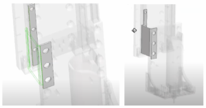
Often, sheet metal is brought into the picture after a multi-body assembly is created.
Now, you as a designer are in charge of using Sheet Metal to connect these bodies together. First, you could start by performing a combination of projecting bodies and creating new sketches in your design. Then, you can create a series of faces, flanges, and bends. However, before you venture down this road, we can actually just start at the Bend command. Inside this tool, you can tell Inventor to make the connection between the edges from each body right off the bat.
2. Creating a Joggle (Contour Flanges)
Sometimes, the easiest looking models are the most frustrating to create, because they look so darn easy! Take this example of a joggle here:
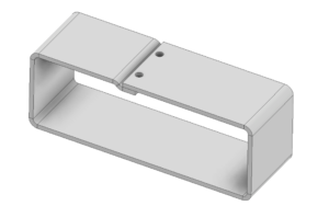
A joggle, or a small offset near the edge of a piece of metal, is sometimes needed when creating sheet metal. It allows two sheet metal parts to overlap and remain flush with each other which can also prevent sliding. To design this, the approach I take is by first creating a skeleton of the edge:
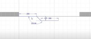
I make sure that the distance is at least the sheet metal thickness (0.12”) so that the part is sliding underneath the other sheet metal part; I also add 0.001” to this value (0.121”) to make sure there is a least a slight gap for the part to be spot welded together. Then, I go to create a Contour Flange of this skeleton which I Join it to the rest of the model and lastly, to ensure that they overlap, I use a regular 3D modeling Extrusion command to extend the other surface above my joggle:
3. Create a Compounded Angle
A compounded angle are multiple angles situated at the same instance; hence the term compounded. There is more than one way to achieve this, this is the way I go about it.
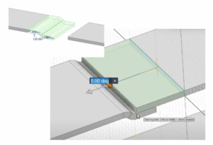
First, create the sketch of the model. Then extrude it as a surface. Now, we use the Angle to Plane around Edge to create a slanted plane (remember this angle value) in which we extend the surface to this point.
After that, use the thicken command (keep in mind we are still in the 3D Model workspace) and give it the sheet metal rule thickness. Make sure to thicken the part outwards so this can work.
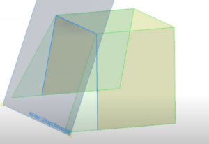
Next, let’s add some bends to the part. Here’s the fun part. Using the Two Coplanar Edges command, you can create a plane that lies on the top edge and the side edge:
Then we can draw rectangular sketches on this plane to represent the flanges we want to create:
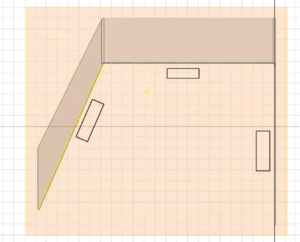
Then, after using the face command to give these sketches a thickness, we can connect them using the Corner Seam command in the Sheet Metal Environment to give us the desired result: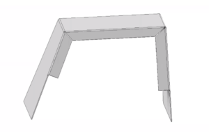
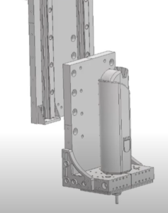
4. Reverse Engineering a 3D Solid Model to Sheet Metal
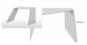
Saving the best for last. We have a customer who receives 3D solid blocks where they are asked to reverse engineer these into something that can be bent into sheet metal. Here is a model similar to that they are receiving:
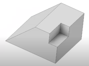
They were currently using the Shell tool, which works at first, however it introduces another series of problems that comes with getting rid of excess material, since Shell is meant for 3D modeling and not Autodesk Inventor Sheet Metal. Therefore, the workaround we recommend is to actually create fillets first and then saving the model. Then, we will be opening up a new sheet metal part and using the Derive tool to bring in that filleted part – as a surface.
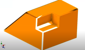
Since this is a surface, we can go ahead and select the fillets and any face we don’t want and Delete Face:
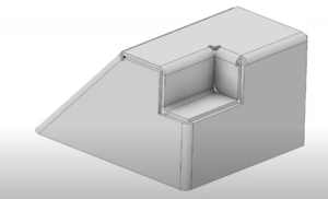
Now you are ready to use the Bend tool in Autodesk Inventor Sheet Metal to connect these evenly-thickened bodies together! Notice that whatever radii you chose for the fillets represents the gap you have between each part. In the future, if you would like a small gap so then you can spot weld the faces together, you can choose the appropriate fillet. Lastly, after adding the bends to the part, you have a sheet metal part you can potentially create, without the headaches of using the Shell feature:
Don’t hesitate to reach out to myself or anyone else on the KETIV team if you want to see how your model can be created in Inventor!
Fill out the form below to subscribe to Autodesk Virtual Academy for free weekly training sessions on your favorite Autodesk topics and products!
[hubspot type=form portal=397692 id=36b3fd8b-6c7f-413b-8d63-d149b5919106]