
Check out this review to understand the past trainings and the next steps that we will cover in this blog.

In the first webinar session of this series, we went over how to get started with Visual Studio. Our second session walks through how to create basic geometry in Inventor API. Finally, the last session covers pushing values to inventor parameters.
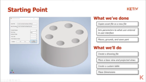
In this blog, we will walk through the process of creating a drawing file, placing a base view and projected views, creating a custom table, and placing dimensions.
Getting started with drawing automation
How to create a drawing file
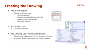
First, we will create the new button using the standard add-in server that we set up in our very first session of this series. Next, instantiate the button and assign it to a ribbon. Then, create a new class along with constructor. Finally, add the drawing code to that class constructor.
How to create a base view and other projected views
There are three different types of views to create: the front view as the base view, ISO view, and top view.
How are we going to get the front view?
Get the sheet from the active sheet that we defined earlier. Call drawing views off of it and add a base view. Next, it needs a position. We’re getting to call off the transient geometry object crank point 2d, and then we just put in the point we want. Watch here for more demo.
The next step is creating a custom table.
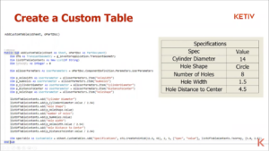
Using the Sub & Function method, grab parameters from that part document that we’ve copied in our previous series and fill in this table. To make a custom table, go into the sheet custom tables.
It will ask for a title, or specifications, and a placement point. Be careful when adding more codes because this can break if your number of rows and the actual number of contents you put in don’t match. Next, you will need to add the table of contents, which we call an array of objects. Here, we
Next, we will add dimensions
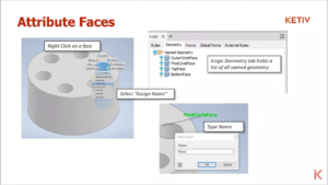
First, we need to attribute the faces. You need to know which faces and drawing lines that we can get as we will automate the drawing. Inventor 2022 added a new option where you can right-click on an object and assign it a name to create an attribute. Once the template is ready, we can add some radius dimensions.
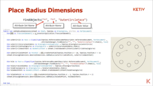
There are three values in the find objects and they correspond to that attribute set name, attribute name, and the attribute value. We put the asterisk in the codes as it can pull out anything that works to that value.
After running the code, you can now see the hole and the outer circle radius as the first 2 dimensions.

Now, to add the widths, you need to go through 2 objects in order to go between those 2 parts, which are the top face and the bottom face. We’ll add linear, dimension type, and vertical dimension type. Once we’re done, you can now run the code, and you’ll see the linear dimensions.
If you’re interested in learning more, or you have specific questions, set up a short conversation with our KETIV Automation Team or contact us at support@ketiv.com