What are Design Accelerators? Autodesk supplies many Design Accelerators within Inventor such as, Bolted Connection, Frame Generator, Shaft, O-Ring, and Spring to name just a few. Today I am focusing on Synchronous Belt Generator.
Why should you use the Synchronous Belt Generator within Inventor? One reason would be to improve your design time and accuracy when using power transmission synchronous belts and to make sure your design and components meet ANSI and ISO standards.
Watch the recent Autodesk Virtual Academy video on the topic below:
About Design Accelerator
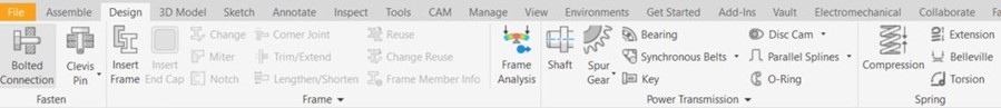
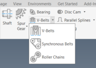
The Design Accelerators in Autodesk Inventor are found within an Assembly file (.iam) on the Ribbon. Click the down arrow and select Synchronous Belts. All three Belt Generators act in the same way. To use any of the Design Accelerates you need to be in an assembly IAM file.
Generating a Synchronous Belt in Design Accelerator
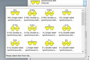
First, choose the type of belt that you want to use.
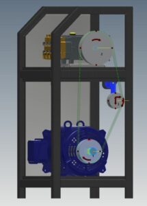
Then, select the surface or work plane that will act as your belt’s midplane.
Adding custom Synchronous Belts
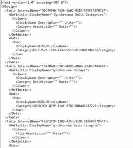
On a side note, if your company uses different belt sizes than the ones provided, you will need to create a custom belt.xml file and import that file. You can find the XML file in this location. C:\Users\Public\Documents\Autodesk\Inventor 2021\Design Data\Design Accelerator\Tables\SBelts
You need to add the name, size, length, and Correction Factor for Belt Length.
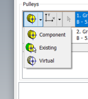
Next, within the Pulleys section, change the type of pulley by selecting the down arrow next to each pulley. You can further define your pulley’s properties by clicking the button with the “Three Dots” next to the drop-down arrow.
The options for how the pulley is going to be represented are Component, Existing, and Virtual. You should also define how the pulley is going to be positioned, whether it is going to be fixed, fixed by position, sliding, driven sliding.
Lastly, we need to specify where in the assembly our belt is going to reside by using the Select Geometry button to locate the pulleys.
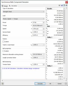
The Calculation tab allows you to refine your design by specifying loads and properties. As you enter the required inputs, periodically click the Calculate button at the bottom of the tab. This will verify that your design is within or out of design compliance. If your geometry and or options within the dialog turn red, this indicates that your design is out of design compliance and requires further modifications. Make sure you always select Calculate after making changes to validate your revised design.