
An Introduction to Inventor Shrinkwrap
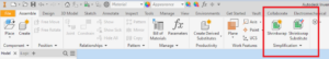
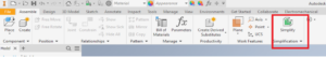
In Autodesk Inventor, there is not a lot of information about the Simplification window and the Shrinkwrap feature. A quick note: starting in Inventor 2022, under the Simplification window, the Shrinkwrap tool is replaced with a new tool called “Simplify”. Think of Simplify as Inventor Shrinkwrap 2.0 version since it has the same ability as the Shrinkwrap tool, but it is easier to use. Nonetheless, if you are using Simplify or Shrinkwrap, learning how and when to use these tools will help you take full advantage of Inventor and ultimately reduce your time spent.
First order of business: What is Inventor Shrinkwrap?
Shrinkwrap is a tool that can be found in any assembly, and its purpose is to simplify a model. The only difference between Shrinkwrap and Shrinkwrap substitutes is that Shrinkwrap will output a simplified Inventor part while Shrinkwrap Substitute will create a level of detail in an assembly.
What are some good use cases for Shrinkwrap?
A reason why someone might want to simplify their model is to protect their company’s proprietary information. By getting rid of details that make the product unique to that company, you can be confident in sending drawings to potential customers and not worry that any trade secrets will get into the hands of competitors.
Another great reason you may want to simplify complex models is to create smaller sizes. If you have an external workflow such as creating factory layouts, when you bring in your models with full details into Factory, eventually when you place too many of those parts inside a Layout, Inventor will slow down significantly. Going through model simplification will bring down the file size by a significant amount, allowing you to place more assets and still have Inventor running at optimal speed.
How to Use Shrinkwrap:
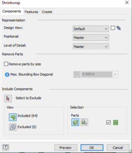
When opening either Shrinkwrap tool, the user interface is the same, so we will be talking about both in unison. The first tab that appears when opening either tool will be “Components.” This window allows the user to select representation information and what components they want to include in the simplification process. Usually, the default settings in the “Components” tab are good enough that it does not to be altered.
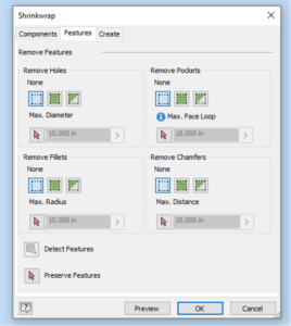
Under the “Features” tab, you can control what set of features are allowed to stay after it is simplified. The simplifications that Shrinkwrap and Shrinkwrap Substitute can handle are removing fillets, chamfer, pockets, and holes. With each removal of a feature, the users get 3 options on what to do with those features. Users can decide to not remove any of those features, remove all the features, or remove all features under a certain size.
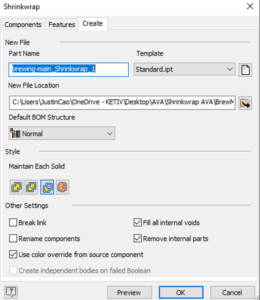
Once you get your details all dialed in, go over to the last tab, which is “Create.” Now, you can select the output of the settings from either Shrinkwrap tool. The most important output on this page is the “Style” selection that is chosen. This is all subjective to the user on what they want to see. Users have the option of single solid with seams, single solid without seams, maintain each solid, and single composite. The thing to note is that the single composite option creates a surface composite body.
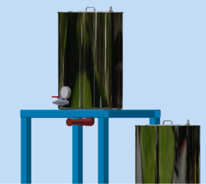
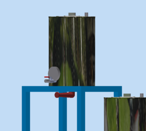
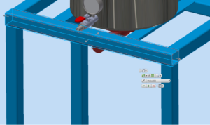
After you are all done with the settings and simplification, the best practice is to preview what you are simplifying before you create the part or LOD. You want to preview so that you have an opportunity to check what is being simplified. If you see that you have missed something, you can go back and add the features that need to be added. If you do not do it this way and decide to create the Inventor Shrinkwrap model right away, there is no way to go back to simplify the model if you missed something. Users would have to go back through the entire Shrinkwrap process. Below are the images of before and after the Inventor Shrinkwrap process, and there has been a notable decrease in model detail.
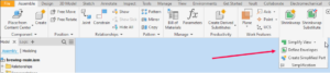
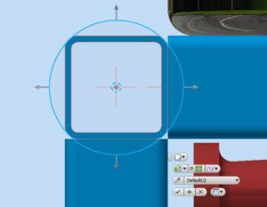
Another tool under the simplification window is “Define Envelope.” In this tool, you can manually select the solids that you want the envelope to cover.
The original shape will be outlined in red, while the envelope shape will be blue. The envelope shape can be switched between either a rectangle or a cylinder. The Inventor Shrinkwrap tool is smart enough to take the exact size the shape is and gives the user the opportunity to make edits to those shapes as needed. For unique geometry that can’t necessarily be bounded by a rectangle or a cylinder, you can get creative to customize the size of the envelope to cover the geometry that you need, or you can create that geometry after a part is simplified.
After all the envelopes have been created, you can go back to the simplification window and create a simplified part. You will have to do your due diligence and make sure that all the envelopes that you created are all there. If you happen to miss a solid that needed an envelope, you will not be able to go back to the “Define Envelopes” tool to create more. If you accidentally created the simplified part and see that you are missing an envelope, in the new part file that was created after being simplified, you can sketch and extrude the geometry you are missing. This is the perfect time to sketch in the complex geometry you were not able to define as an envelope. Please note that if your goal is to have small file sizes, as you add more complex geometry into the Inventor Shrinkwrap part, you are increasing the file size.
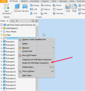
For the last step, if you want your file size to be small, you will have to break the link between the simplified part and the assembly it was derived from. Once that link is broken, that is when you will notice that the file size has been significantly reduced.
For a step-by-step video on this process, check out the Autodesk Virtual Academy on the topic, The Power of Inventor Shrinkwrap or click the thumbnail below!
Sign up for KETIV’s weekly webinar, Autodesk Virtual Academy to see more updates for Autodesk manufacturing software!