101 - BOM and Part Lists
This comprehensive guide is intended to help users of Autodesk Inventor understand the capabilities and use of the Autodesk Inventor Bill of Materials (BOM) capabilities, and how they relate to maintaining Parts Lists and interaction with Autodesk Vault software, ERP, and PLM systems. Each section focuses on a specific topic related to Inventor Bill of Materials.
Level 200 will look at intermediate topics dealing with BOM management. Level 300 will look at more advanced topics such as Virtual Component use and how to make the most out of Part List capabilities.
BOM 101 – Bill of Materials and Parts Lists
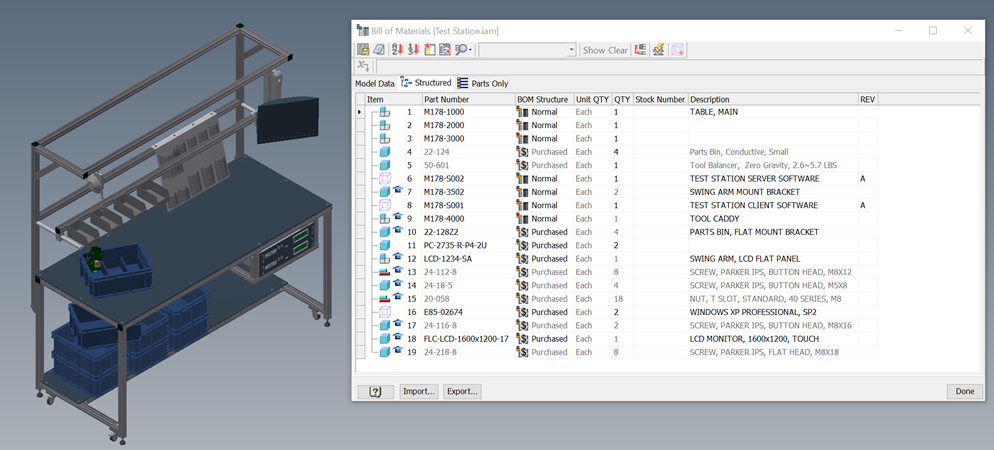
It can often be confusing to understand the Bill of Materials that are in Inventor Assemblies and Parts Lists that are in drawings. The two are related but are not the same thing.
The Bill of Materials inside Assembly is considered the master list. Parts Lists in drawings are considered a “report” generated from the Assembly Inventor BOM. Systems like Vault Professional will not look at the drawing parts list when creating Items for Inventor BOM’s that are used downstream in PLM or ERP systems, they will look at the Assembly BOM.
So key differences between the two related capabilities are as follows:
Bill of Materials
- This is a master list of components and their properties that make up an assembly.
- It is stored in the assembly file. There is only one BOM per assembly.
- There are 3 views of the BOM: Model, Structured, and Parts only (you can refer to BOM 102 and BOM 103 for more)
- It always reflects the entire assembly and its current state. For example, all children are always accounted for, quantities are kept up to date, etc.
- There is little to no formatting in an assembly BOM. You use features like formatting, filtering, etc. for editing purposes only.
- It maintains the Item numbers used by Parts Lists, to make sure Item Numbers consistent across all drawing part lists and drawing files of the assembly.
- You can see all edits made to the Bill of Materials in Drawings and compatible Data Management system such as Vault Professional. The edits are saved to the Assembly file.
Parts List
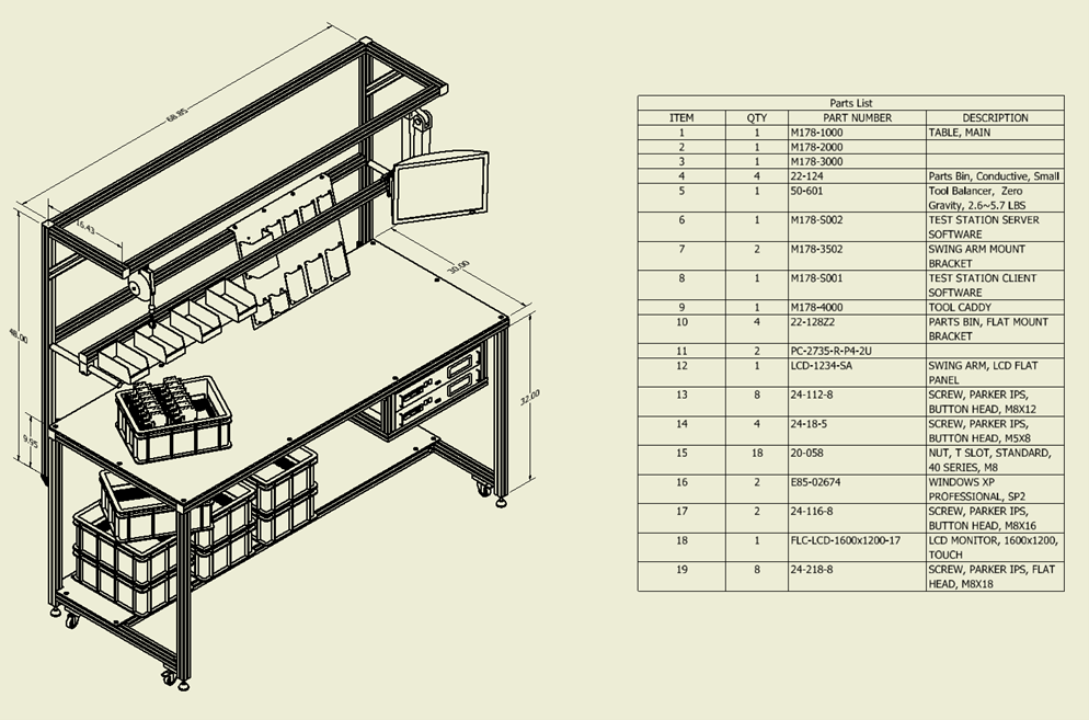
- This is a drawing based “report” generated from an assembly’s Bill of Materials. It is stored in the drawing file and represents the parts and assemblies displayed on the drawing.
- It offers capabilities such as formatting, filtering, summaries, etc.
- You can create multiple Parts Lists that have different filtering and sorting from the same BOM and get different information.
- Each Parts List can have different numbering, sorting, etc.
- Edits in a Parts List are local drawing overrides to the Bill of Materials. You cannot see edits in other drawings or in any Data Management application such as Vault Professional that is looking at the assembly’s complete BOM.
So why can you edit Parts Lists and override information?
You can edit parts lists due to backwards compatibility with older versions of Inventor. BOM was introduced in Inventor 10. Before that, Inventor only had parts lists in drawings and allowed users to edit parts lists to override information. To maintain that backwards compatibility, editing had to be left in Parts Lists. If you ever wonder whether to edit a parts list or a Bill of Materials, it is almost always correct to edit the BOM.
In conclusion
A Bill of Materials is the master list of components that make up that assembly. This includes the properties of the components such as part number and quantity. A Parts List is a drawing report generated from data based on the BOM. Edits to a Parts List are not seen in other drawings or in the BOM itself.

Featured Resource
Automation Starter Kit
Automation helps people meet design challenges and presents an opportunity to do better. By pairing their imagination with new forms of computer automation, people can design better products, fabricate them faster, and make work more meaningful.
102A - Structured, Parts Only, and Model Data View in BOM
Autodesk Inventor users often try to make their assembly structure represent a BOM when a 3D assembly looks so much like a BOM. They are closely related, but there are construction techniques and tools that make the assembly structure different from the true BOM.
- A Skeleton Part is a single part with master geometry that drives other parts.
- Space Claims, sometimes referred to as “Keep Out Zones”, is typically a simple part.
- A Hardware Set makes it easier to assemble. In other words, it is easier to place an assembly with a nut, washer, and bolt 50 times rather than place 3 components 50 times each.
- A purchased assembly is a hinge that is modeled as two parts (to allow it to “bend”). The parts should never be in the BOM.
What are the structured, Parts Only, and Model Data View in Bill of Materials?
These types of components cause problems for Bill of Materials. You need to create a component or assembly structure in a way to make it easier to maintain the assembly model and represent it in a bill of materials differently (or have it not show up at all in the BOM). This leads to three different “views” in Autodesk Inventor.
Model Data View
This is the internal, unmanipulated view of all the parts and assemblies in a BOM. It is never used directly by drawing Parts Lists, Vault Items, etc.
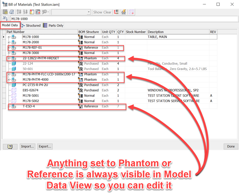
The Model Data View exists simply to make it easy to edit of BOM data. As described in BOM 103, if you set a component to “Reference” or “Phantom” as it’s BOM Structure, it is removed from the Structured View and/or Parts Only View. If the component does not show up in the BOM editor, you can’t edit it. Therefore, the Model Data View exists to make sure you can always get to every component while in the BOM Editor.
- You can see every component, including the “fake” assemblies (Phantom), the skeleton parts (Reference), etc.
- The Model Data View is never meant to represent your actual BOM. Structured Views are the most common view of a BOM.
Structured View
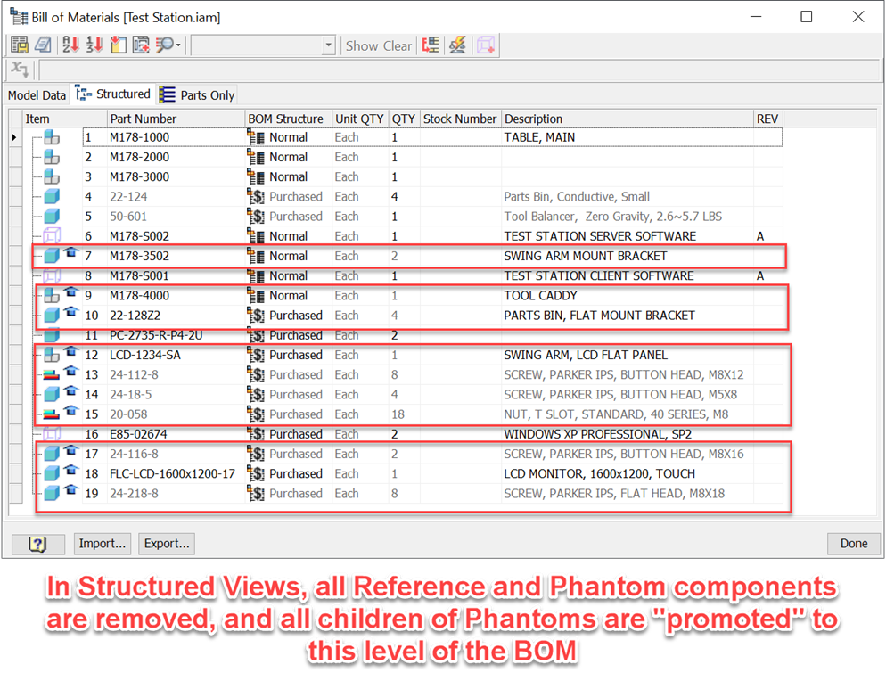
Structured Views are the most common type of Bill of Materials that represents your finished design. This is the bill of materials that Data Management systems, like Vault Professional, work with. As you can see in the image above, anything that is set to Reference (along with ALL child components) are removed entirely from this view. Anything set to Phantom is removed, but all of its children are “promoted” and Quantities are updated so they are correctly made up in BOM.
So in Structured Views:
- It filters out all the “construction” items used to design the CAD model (BOM Structure = Phantom or Reference). It does not show skeleton parts (Reference). Hardware sets (Phantoms) are shown as individual components, and child components of purchased assemblies are never accounted for.
- In Inventor, a BOM Structure property is used to communicate a component use in the BOM.
- This BOM is sometimes referred to as the “Design BOM”
Parts Only View
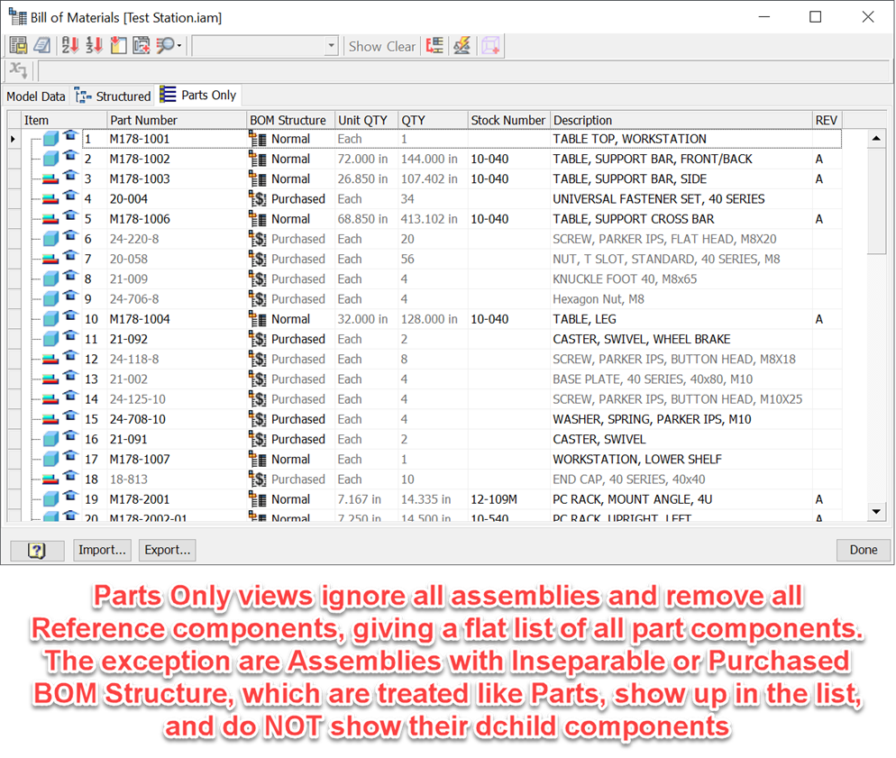
So what is a Parts Only View? There are two generic ways of looking at a BOM:
- Structured – you see the parent-child relationships of the assemblies/sub-assemblies. Some people call this an “Indented” BOM view
- Flat – there is a single row per component; no parent/child relationship is shown, and it shows “ALL” components from the bottom to the top of the assembly. Basically, all assemblies are ignored.
Parts Only views are typically used for purchasing. While they were more common in the early days of CAD, with the advent of modern ERP/PLM systems they are used less frequently. Parts Only views require extra property caching, so they are off by default to help with file size and performance.
Reference and Phantom are also included in Parts Only View, though Phantom has no actual use because assemblies not Purchased or Inseparable are ignored.
Note: The BOM Structures “Purchased” and “Inseparable” are used exclusively with Parts Only BOM Views. See BOM 102b for more information on their use.
Summary
You can look at Bill of Materials Data with different BOM Views that are foundational to maintaining and editing the information. Model Data View is your view ignoring BOM Structure, ensuring that you can work with all information you need. Structured View is the most common and flexible BOM view. Parts Only View entirely ignores assemblies and gives a flat list of all part components in a BOM.
102B - 5 Structure Types for Bill of Materials
There are five BOM structure types that communicate a component’s use to the Bill of Materials. BOM Structure for a component can be found by going to the Document Settings and selecting the Bill of Materials Tab. Each of the BOM Structure types is described below.
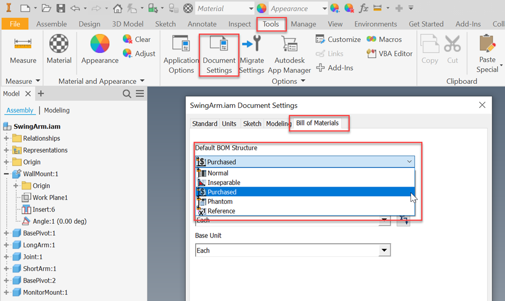
5 types of Bill of Materials structures
Normal
Another type of bill of materials is Normal component. Normal component has no special handling in the Bill of Materials. This is the default structure for a component. Most manufactured parts and assemblies are “Normal” components.
Phantom
A Phantom component is a physical part of a design that does not show up in Inventor Bill of Materials. An example is an assembly made for placing components. It’s easier to place an assembly with a nut, washer, and bolt 50 times rather than place 3 components 50 times each.
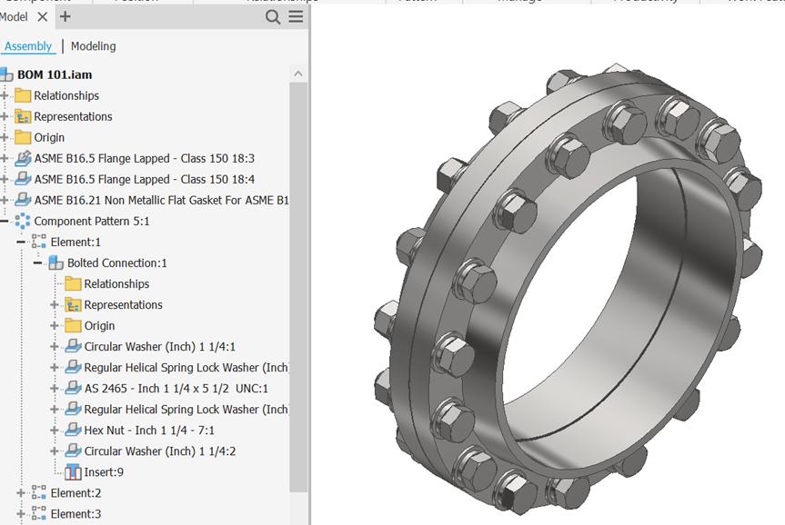
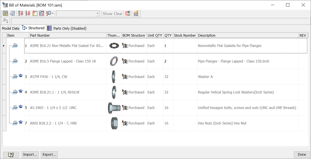
As can be seen in the images above, a Bolted Connection Assembly holds a bolt, a nut, and 4 washers (2 flat, 2 locking). It is a Phantom Assembly, so it does not show up in the BOM, only the children do, at the correct patterned quantities.
All children of a phantom assembly are shown in the BOM Structure as if they were assembled one level above their actual placement. This is indicated with an arrow on their icon in the BOM editor.
When you place a Phantom component on a drawing, it is displayed like a Normal component.
Reference
A reference component is purely a construction component, or a component used for aesthetic reasons. Common uses for reference components are:
- A skeleton part or assembly used in skeletal modeling
- A visually aesthetic component like a box full of circuit boards on a work bench
- A reference component like a car fender placed inside a spot-welding machine to show how the reference component is meant to be oriented while the spot welding machine is in operation.
Reference Components and all their child components are ignored by the Bill of Materials, do not participate in mass calculations, and have special drawing view properties.
Note: BOM Structure is typically set in the document settings of a component, which means all occurrences follow that structure. Reference is the only BOM structure that can be set as an override inside an assembly.
Inseparable
An Inseparable assembly is an item like a Weldment that you cannot take apart once it is assembled, and therefore is a single line item in a BOM. You can use this BOM structure only in Parts Only views of a BOM.
In a Structured BOM Inseparable assemblies behave like Normal assemblies, showing all children.
In a Parts Only BOM, the Inseparable assembly itself shows up as a row, representing the completed assembly as a single part. None of the children show up in the Parts Only view, except for children marked as Purchased.
Purchased
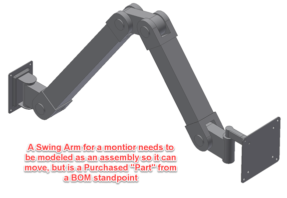
A purchased assembly is an item like a hinge, where the child components will never be purchased or assigned a part number, but are required in order to model the design correctly (such as motion).
In a Structured View, purchased assemblies behave like Normal assemblies, showing all children.
In a Parts Only View, purchased assemblies show up as a row, representing the completed assembly as a single part.
Isn’t that what an Inseparable assembly does? Yes, so what is the difference?
Purchased Child components of an Inseparable assembly WILL show up in a Parts Only BOM. For example, Threaded Inserts in a Weldment need to be accounted for as purchased parts.
Some Data Management systems, such as Vault Professional, need to know the difference between Inseparable and Purchased assemblies. You need to acquire Purchased, while you fabricated Inseparable. This gives you a way to show that difference.
Summary
The different structure types of bill of materials provide a method for using common construction techniques while maintaining an accurate Bill of Materials for downstream consumers like drawings and Vault Professional.
103 - How to Specify Quantity in Bill of Materials
Inventor BOM lets you specify a quantity for components that are something other than the discrete number of occurrences (1, 2, 3, etc.) of the part file in an assembly. You can specify quantity in terms of Length, Volume, or Mass.
There are three basic properties that represent the quantity of a component, the Base Quantity, the Base Unit, and the Unit Quantity. These are document settings on the Bill of Materials tab in the Document Settings dialog for the part. They can be set using the Assembly Bill of Materials dialog by adding the Base Quantity and Base Unit columns to the grid.

Base Quantity

Base Quantity is the “raw” quantity for a single instance of a part. By default, this is “Each”, which means that every occurrence of the part in an assembly adds “1” to the total quantity.
To have a base quantity that is either length, volume, or mass, you must set the Base Quantity document setting to be any model parameter, user parameter, or imported parameter. Only parameters that have a value as units of length, volume, or mass are valid. The quantity will update with the parameter, and equations can be used in the parameter
If you want the quantity to be the final length plus some amount of waste for a cut (say 1/16 of an inch), you can set up a parameter that is called “PurchasedLength” for your Base Quantity and set PurchasedLength to be equal to Length + 1/16.
Base Unit

You can think of the base unit as the Unit of Measure for the part.
You may have to design something in one valid unit, but you really report it in another. For example, you may purchase a structural steel beam in inches have to cut it to 55 millimeters. You want the quantity to be in inches, so you select inches as the Base Unit.
Unit Quantity

Unit Quantity is just the Base Quantity formatted with the Base Unit. For example, if the Base Quantity is 30 inches, and the Base Unit is millimeters, the Unit Quantity will be 762 mm.
Quantity Overrides
You can override quantities of a component in an assembly to be a static value. Start the assembly Bill of Materials dialog, and simply type the value into the Quantity cell for the component. To restore the calculated value, right-click on the Quantity cell and select Calculate Quantity.
Summary
Autodesk Inventor Bill of Materials allows you to set up quantities other than discrete addition, which better reflects the true Bill of Materials. Use the Base Quantity to get the raw amount needed, and the Base Unit to keep it formatted properly for communicating the quantity to all your drawings and to Data Management systems, such as Vault Professional. Quantities can even be manually set to a static value in the assembly BOM.
201 – What are Equivalent Components on my BOM?
his blog will start the series of intermediate blogs for Bill of Materials (BOM). The series will help users of Autodesk Inventor understand the capabilities and use of the inventor Bill of Materials, and how they relate to maintaining Parts Lists and interaction with Autodesk Vault, ERP, and PLM systems.
What are Equivalent Components?
A common problem with CAD models is having duplicate files that are supposed to be the same component. This can happen for a few reasons:
- You imported data, and the import creates multiple files for the same component or includes files that are equivalent to your own files such as screws and nuts.
- You accidentally created two parts that turn out to be the same, but replacing one with another could be problematic due to assembly constraints, data management headaches, etc.
- Furthermore, you created a part or assembly for a purchased component in your design (say a cylinder), and someone else creates the exact same component for their design.
So, how do you tell all drawings and Autodesk Vault that these two different files are actually the same component (i.e. they are equivalent)?
Part Numbers & Equivalent Components
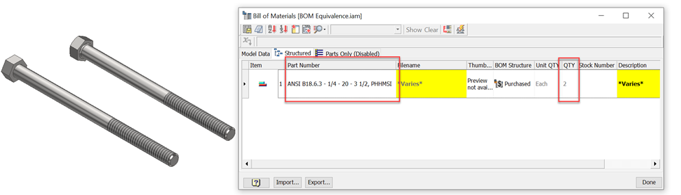
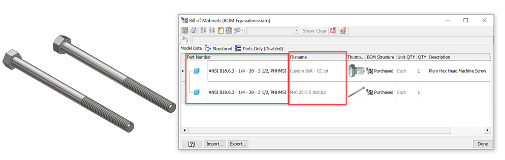
Inventor BOM uses part numbers to determine if two or more parts are “equivalent”. Part numbers tend to be unique; two different items usually have different part numbers.
So, if two or more files/components have the same Part Number, by default, BOM performs a “roll up” or “merge” on equivalent components, making them a single line item in the BOM.
Rules for Equivalence

The basic rules Inventor uses for equivalence are:
- When Inventor sees two or more components that have the same parent assembly and are the same part number, the BOM considers them to be the same component and treats them as the same component.
- Components with a blank Part Number, or a part number made up of “white space” characters such as spaces, are never equivalent
- If a Part and an Assembly are equivalent, then the resulting roll-up looks like the assembly (i.e. you get a line item with a quantity of 2, and that line items has the assembly’s child components in the BOM)
Cases Where Equivalence is Not Used
The Equivalence Rules are always on in Inventor’s BOM. However, there are cases where more than one file has the “same” part number, but should not be treated as equivalent:
- Cut Length components such as tubes, pipes, structural steel, wires, etc. often have a single part number for every component
- Some common items such as fasteners tend not to have a part number, and use some “generic” entry such as “N/A”, “-“ etc. for their part number to indicate this.
Inventor can handle these cases in 2 different ways.
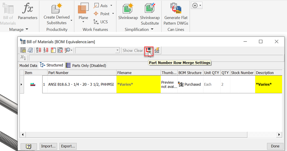
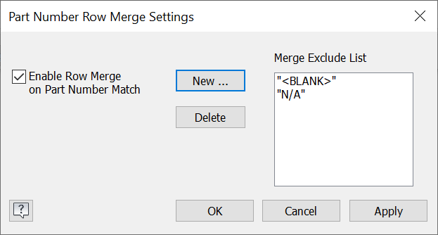
The first is in each Assembly document you can set a list of values to ignore when evaluating equivalence. Open the BOM Editor, then select the Part Number Row Merge Settings button. In the dialog you can add string values that the merge should exclude from acting on. You can also turn off merging for the assembly document entirely.
In addition, Inventor has the concept of a Stock Number, which is discussed in BOM 202.
Summary
Inventor uses part numbers to solve a common problem with a Bill of Materials, how to tell that two or more files on disk are the same component in inventory. This helps to reduce the number of duplicate items within data management systems, such as Autodesk Vault Professional.
202 - What are Part Numbers and Stock Numbers in BOM?
What is a Stock Number?
Part Numbers are usually a unique way of identifying a part in Inventory. When a component gets a Part Number, this is a way of making it unique. However, common practices with items such as cut-length components and fasteners are not straightforward.
With cut-length parts, the part number is often a common “stock” that individual pieces are cut from. It is meant to represent the common stock identifying part number.
How to Use Stock Numbers
To use the iProperty requires setting up drawing Parts List styles to substitute it for Part Number. By doing this substitution and leaving the Part Number blank in each of your cut-length part files, the BOM will NOT merge the cut-length stock together (so each length will be its own line item), but the Parts List will show it as the Part Number for each. Follow these steps:
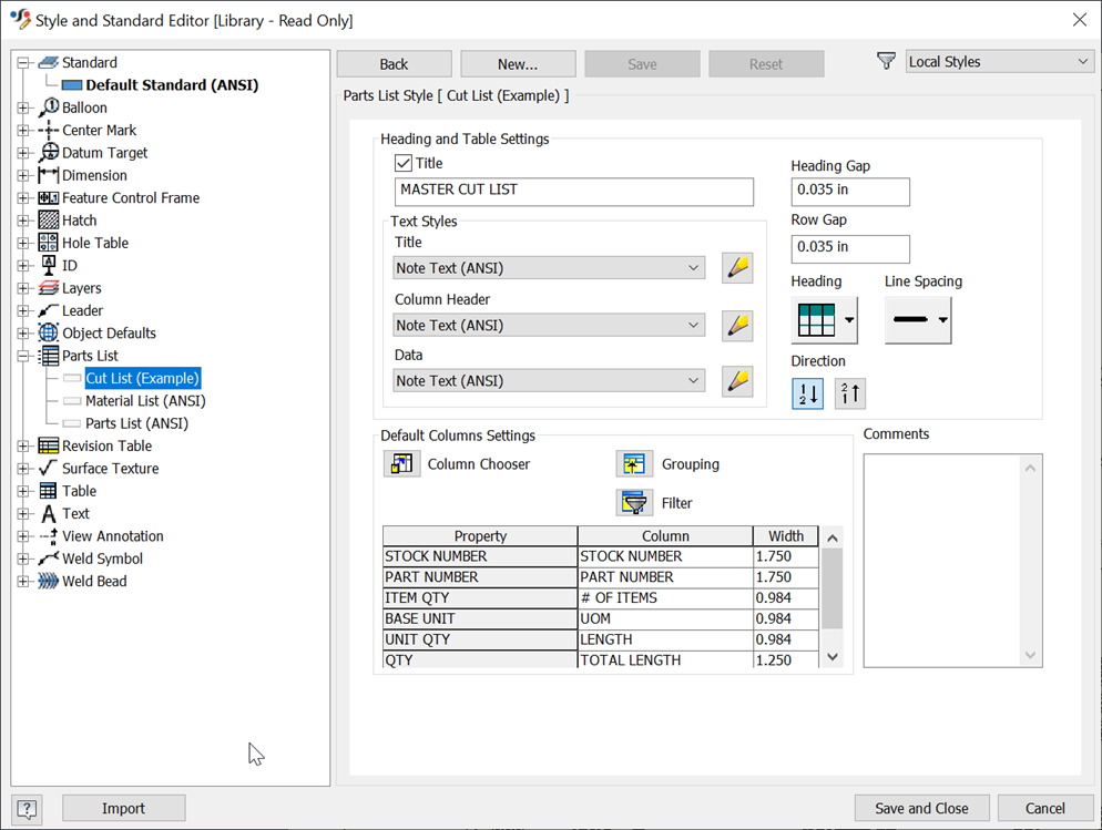
- In a drawing, choose Manage -> Styles Editor…
- From the Styles Editor, choose a Parts List style to edit
- In the Default Column Settings group, in the Property column, double-click Part Number (or right-click and select Format Column).
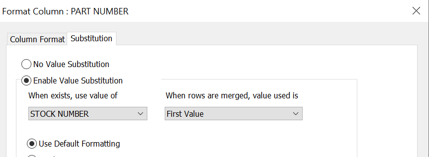
- In the Format Column dialog, select the Substitution tab. Click Enable Value Substitution
- In the “When exists, use value of” dropdown, select Stock Number if it is listed. If it is not listed, select Browse Properties… and select Stock Number from the list of properties.
- Click OK to exit the dialog and save the Parts List style. You can now apply this style to all existing and new Parts Lists, and the Stock Number will be used if it exists. To use it in other drawings, you can save it to a Style Library to make it available to all drawings.
iParts, Part Numbers, and Stock Numbers
If you are using iParts that do not generate unique part numbers for each iPart member, this can cause some unwanted rollup. To clean up unwanted rollup, follow these steps:
- Open the iPart Factory and open the iProperties for the factory
- Copy the Part Number to it, and delete the Part Number entry
- Save the iPart Factory.
On the next assembly update, all iPart members generated from the factory will update to have their Part Numbers blank and their Stock Numbers set the same as the factory. Setup Parts Lists as described above to show the Stock Number instead of the Part Number in Parts List.
Summary
The Stock Number is a property that is used to identify components that need the same part identifying number or property but should not be considered equivalent components. Parts Lists can take advantage of it by formatting the Part Number column with a substitution.
203 – What are Bill of Materials Rollup Errors?
When Autodesk Inventor Bill of Materials see two or more components that are equivalent, it creates a “rollup” of the items, showing them as a single row in the BOM and in the resulting Parts Lists. In this article, we will explain more about BOM rollup errors. Stay tuned for our advanced “Level 3” BOM series coming soon!
What are BOM Rollup Errors?

*Varies* cell
If the properties of the rolled-up components do not match, Inventor does not know which value to use in the Bill of Materials as the value to communicate for the resulting rollup. Since the components are supposed to be the same component, Inventor requires that the iProperties be the same.
For example, three equivalent parts have three different Description iProperties: “10-32×0.5 Hex Head”, “10/32-1/2 Hex Cap Head”, and “#10/32 Hex Cap – 0.5 in Long”. Inventor does not know which description to actually use, so they must be the same.
Setting the properties to be the same value is easy.
- Start the Bill of Materials dialog from the assembly or by right clicking on a Parts List and selecting “Bill of Materials…”
- Find the rollup row. Properties that conflict are highlighted in the BOM dialog.
- Click in the cell that says *Varies* and type in the desired value. The value will be saved to all the components in the rollup.
Quantity Rollup Errors
Quantity has a special handling with Rollups. The rules for handling quantity during a roll up that Inventor follows are:
- When two or more components are in a rollup, they must have a compatible Base Quantity:
For Example: All must be units of Length, Volume, Mass, or Each
- The units do not have to be the same (i.e., one can be inches, and another can be millimeters), as long as they are the same basic type of unit.
- When the unit types match, but the units do not, Inventor chooses the unit from the first item it encounters when creating the rollup
Inventor will warn the user if rollup errors in quantity occur before printing or publishing a drawing. To resolve these errors, change the Base Quantity of all components in the rollup to all be the same basic type (Each, Length, Volume, or Mass) as described in BOM 103.
Summary
BOM rollup errors such as *Varies* occur when two or more components with the same part number are merged by the Bill of Materials and one or more Properties do no match between the components. For standard iProperties, the user can edit the rollup and type in the value they want, and it will be saved to the components in the rollup errors. For Quantity errors, edit the Base Quantity of the components so they have compatible unit types such as Each, Length, Volume, or Mass.
301 - Inventor BOM Virtual Components
What are Virtual Components?
There are usually parts that must be accounted for in a design that do not require a physical model in the assembly. Examples are:
- Software that is installed on a system
- Bulk items such as water, fuel, oil, or air
- Fasteners (to save capacity and time)
Inventor provides a means to account for these non-modeled components: Virtual Components.
The Advantages of Virtual Components
They are non-graphical components that you can add to an assembly to represent un-modeled components. To create it:
- In an assembly, start the Create Component command.
- Select Virtual Component in the dialog and select OK
They have several advantages:
- No file –they do not have a file, they are simply a collection of properties that are saved with the assembly file they are created in.
- They are automatically added to the assembly Bill of Materials. They are seen in all drawings of the assembly and can be seen in Data Management applications such as Vault Professional. Virtual Components can have a BOM Structure property like real components.
- Virtual Components can have a quantity like standard components. Right-click on the Virtual Component in the assembly browser, choose Component Settings… and change the Base Quantity and Base Unit as described in BOM 103. Virtual Components use parameters from the assembly.
- They can be copied and pasted in an assembly and between assemblies. They can also be patterned to keep quantities up to date.
- Virtual components can have a Mass that is used in the mass calculations. However, all of them have a position of (0,0,0) in an assembly, so use caution when using them.
To create a Virtual Component, while in an Assembly file, select the Create command. In the Create dialog, give the component a name, then select the Virtual Component checkbox. This will create the virtual component and add it to the assembly model browser. Once there, you can right-click on it to access its iProperties or Component Properties.
Custom Parts
Note: Custom Parts are legacy capability from before Inventor had a formal Bill of Materials inside of Assemblies. Custom Parts, the predecessors, are a way of adding a line item to a drawing Parts List.
Custom Parts have a major drawback which is a local override in the drawing. They are not in the assembly Bill of Materials, so they cannot be seen in any other drawings or in any Data Management application such as Vault Professional. Therefore, it is NOT recommended to use them.
Summary
Virtual Components can be used to represent items that are not actually modeled in an Assembly. They live in the assembly, so they are seen by drawings and data management applications such as Vault Professional.
302 - Parts List Grouping in Bill of Materials
What is Parts List Grouping?
Parts List Grouping in Inventor BOM is used to create summary rows for items that have similar characteristics. Grouping maintains individual identity of the components for Ballooning. It groups these items together and provides a means to create a summary row for the items.
Grouping Setup
To set up Grouping in a Parts List Style:
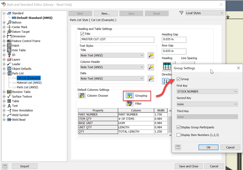
- In a drawing, choose Manage>Styles Editor… Choose a Parts List style to edit
- In the Default Column Settings, choose Grouping
- From the Grouping dialog, turn grouping on and define up to three Keys based on iProperties
- Select OK, save the style. You can now apply the style with the grouping turned on to a drawing parts list. Save the style to a Style Library to reuse it in all of your drawings.
Grouping Keys
Keys are iProperties that you define for grouping purposes. When two or more components in the Parts List have Keys that match, they are considered part of the same group.
For example, lets take the following four components:
- Part A.ipt, Part Number: A-113, Stock Number: 32×511, Description: “Class A Part”
- Part B.ipt, Part Number: A-114, Stock Number: 32×511, Description: “Class A Part”
- Part C.ipt, Part Number: B-111, Stock Number: 32×511, Description: “Class B Part”
- Part D.ipt, Part Number: B-112, Stock Number: 32×511, Description: “Class B Part”
If Stock Number is the only key, all four parts will belong to the same group. If grouping is set up with two keys: Stock Number and Description; then Part A and Part B will be one group, and Part C and Part D would be a second group. Each group gets its own summary row.
Grouping Options
Grouping has two options:
- Display Group Participants – when off, only the summary row is displayed for the group. When on, both the group participant rows AND the summary row are displayed in the Parts List
- Display Item Numbers (1, 2, 3) – When on, the summary row displays the Item Numbers of the components that are grouped.
Summary
Parts List Grouping allows the user to create summary rows of components in a Parts List without losing the individual ballooning identity of those items.
303 - How to Create a Cut List in Drawings

How to Make a Cut List in Drawings
With the quantity capabilities of BOM, an associative cut list for cut-length components can be created for drawings. Steps for creating a sample cut list are outlined below. In this example, we are assuming each cut-length item has a unique part number as well as a common stock number to represent the stock. If a common stock number is used, substitute stock number for part number when setting up the Part List style (see BOM 201b).
Note: An example of a cut list can be found in the Inventor sample files installed with Inventor. It is in the Test Station Assembly samples.
Make a Part List Style for a Cut List
- In a drawing, choose Manage>Styles Editor… Choose a Parts List style
- Right-click the style and select New Style. Name the Style “Cut List”
- In the Heading and Table settings, change the Title to Cut List
- Choose Column Chooser from the Default Columns Settings
- Add the following columns and select OK, change the Column name to match the names in quotes.
- Item “Item”
- Stock Number “Stock Number”
- Part Number “Part Number”
- Base Unit “UOM”
- Item QTY “# of Items
- Unit QTY “Length”
- QTY “Total QTY”
- Select Grouping from the Default Columns Settings.
- In the Group Settings dialog, turn Group on, set the First Key to Stock Number, and turn on Display Group Participants
- Save the Style and exit the Style Editor.
Create the Cut List
Now that the Cut List formatted Part List style is ready, the cut list can be generated.
- Create a view of the assembly and create a parts list for it.
- Select the part list and apply the “Cut List” style to it
- Right-click and Edit the Part List
- Sort the Part List by Stock Number and then by Part Number
- Select all components that are not cut-length items, Right click and turn off their visibility.
- Select OK to finish creating the Cut List.
Summary
Using the quantity document settings for components, along with Grouping in Parts Lists, cut lists with summary rows of total stock required can be created for drawing documentation. The cut list will be updated as the design changes and lengths of cut length items change.