
Having trouble getting started with Inventor’s Tube and Pipe? Or are you looking to implement a standard process and procedure in your companies’ environment. Defining a standardization between Content Center, Tube and Pipe Styles and File Naming Defaults will ensure success in the utilization of the toolset.
Content Center
To get started, lets address the elephant in the room “Content Center”. As you may or may not know, the tube and pipe environment pulls components directly out of content center into your pipe routes. With a standard installation of the software, Autodesk Inventor will install standardized libraries such as ANSI, DIN, ISO and others for use within your tube and pipe routes. The standard libraries are a great way for you to get going in the environment. What you may notice is the generic component information within your Bill of Materials. Creating a custom content center library will enable your ability to standardize property data directly into your assemblies and drawings. With the end goal being able to populate an accurate Bill of Materials that leverage your custom part numbers, stock numbers and descriptions.
For more information on customizing content center, take a look at our previous blog post on “How to Add properties and Parameters to Content Center Families”
Pipe Styles
Next, you will want to begin creating tube and pipe styles which dictate what components make up your pipe runs. An example of these can be represented as a single line item on a piping specification sheet that may be driven by a company or customer standard.
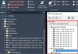
For each unique style that you create, it is best practice to create an identifiable style name that list key information like class rating, pipe size, pipe schedule, or material type. This will enable designers to properly insert and utilize the correct styles in their projects. Once you have given your style a unique name, you will then map each fitting component to a specific family that may exist in your content center library.
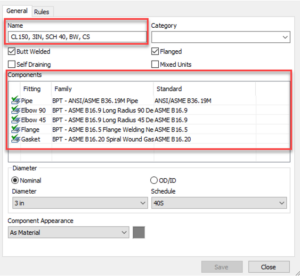
“Insert Custom Content Center Here”…..In case you skipped the first part of this blog post, this is where creating a custom library becomes handy. In the image above you can see that the fittings are being mapped to a component from the custom library that has unique property data to ensure value in your part lists.
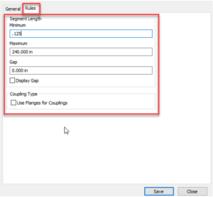
After the components have been mapped in the style editor, you can specify rules that drive the behavior of your pipe runs. An example of this would be whether production requires gaps between piping and components for welding or if you need to butt up multiple pipe segments due to length constraints.
Another way you can expand further with this process is creating an assembly file that is dedicated to maintaining and managing all centralized pipe styles. It shall allow an administrator to easily update and expand upon styles that may require modifications driven by a specification change. Once these styles have been modified or updated, the administrator can then export the updated style and relocate it to a centralized location for use in existing and new projects.
File Naming Defaults
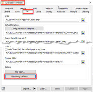
Lastly, File Naming Defaults is a new addition for tube and pipe in Inventor Professional 2021. Determining file name schemes up front will increase overall productivity inside the tube and pipe environment. You will first want to access your application options > select the file tab > then select file name default at the bottom under options.
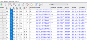
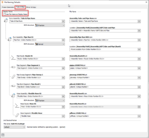
Once you have selected the File Naming Defaults options, a new dialog box will open, navigate to the top, and select the Tube & Pipe tab. From here, you will see a list of naming schemes that you can configure. For example, by default Assembly.Tube and Pipe Runs.iam generate the name by inserting <Assembly Name>.Tube and Pipe Runs, in another case it may be more beneficial to title the assembly by the Project Name property or even Date Month MM.
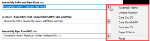
Pipe routes can also take advantage of this by ensuring a unique file name with Index Number property inserted into your naming default. The index number will increase as you generate new pipe routes in your project. Additionally, turning on the check box for Use File Name as
Display Name will provide visibility of your defined naming defaults directly in your model browser tree.
Since application options are specific to a user’s machine, an administrator can configure the naming defaults and export their application options via .xml format and save it to a centralized location. Users can then import the ApplicationOptions.xml file and retain the standardized naming schemes.
In case you missed the webinar, Click the link below and be sure to subscribe to Autodesk Virtual Academy. Using Tube & Pipe in Inventor Professional 2021 and Inventor Tube & Pipe Advanced Workflows