
Sketch symbols are used to create custom sketch symbols that are unique to the industry you work in, so you can communicate your design intent. The name “sketch symbol” may be misleading because a lot of users might think the sole purpose of this tool is to just sketch symbols. If you are limiting the tool to only one-use case, this will prevent your ability to make advanced drawings efficiently and effectively. In this blog we will cover use cases of sketch symbols, such as title blocks, text, model details, model dimensions, and images.
Title Blocks and Text
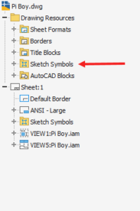
Open a drawing and expand the “Drawing Resources” folder in the model browser. You will see a “Sketch Symbols” folder and right-click on that folder and click on “Define New Symbol” to create a new sketch symbol.
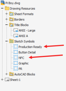
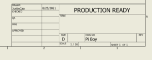
Now, we can create our sketch symbol. For example, in our title block, there is a section that will be used to tell what stage the drawing is at. It will either say “NOT FOR CONSTRUCTION” or “PRODUCTION READY.” We will add a text box to our sketch and add the text above. Note that we will have to create two separate sketch symbols: one for each text. Once you are done in the sketch environment, finish the sketch
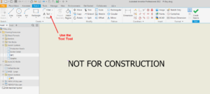
Once you have both sketch symbols ready, we can start to place it onto our drawing in the appropriate location.
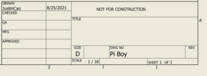
You may be wondering why anyone would use a sketch symbol to fill out fields in a title block? If you have a custom title block, most likely you are using prompted entries to fill out those fields. Sketch symbols are the best option because they provide a seamless process when updating allow updating the title blocks. Once the sketch symbol is created, it can be constantly reused. This now allows engineers and drafters to place a symbol in a few seconds rather than typing, which could potentially lead to spelling errors. This is extremely beneficial especially if there are certain fields in the title block that has longer phrases.
Model Detail and Dimensions
If you have details in your model that you would want to point out, usually we would use a section view to show this. The downside to using a section view is if your drawing has a lot of dimensions on it, everything can become cluttered, making the drawing hard to comprehend. This is also very helpful if there are parts that consistently need to have the same details on different drawings. In our example, we will be creating a button detail within a sketch symbol.
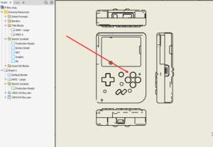
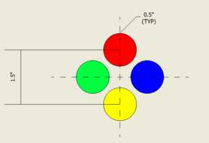
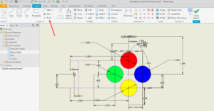
Start a new sketch symbol and sketch the geometry you want. When sketching the geometry, there are 2 options. The easiest method would be making the sketch the same exact size and then scale it up or down to make it bigger on the drawing. Using the second method, it can be an arbitrary size, so it fits on the drawing sheet. Either method will work for this case. The sizing will not matter because you will never see the actual dimensions unless you are in the sketch itself. Once the sketch is done, you can add further detail by hatching closed sketches to add colors.

We can also add lines to the sketch and a text box to show some dimensions. When inputting the dimension into the text box, it will not matter if you make the sketch dimension 1:1 or if you make it an arbitrary dimension.
When creating sketch symbols, the insertion point may not always be where you want, especially if the symbol does not have symmetric geometry in both directions. The easiest way to get the insertion point to be exactly where you want it is to use the point tool in the sketch window.
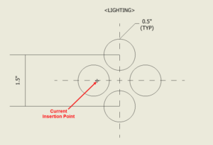
Select the point tool and place it wherever you want the insertion point to be at. It can be snapped to existing geometry, or it can be placed somewhere arbitrary. When it is snapped to existing geometry, you may not see the point visibly, but it is there. Press on that point, and then you can set it as the insertion point and save the edits to the sketch symbol.

Now, when you try to place the sketch symbol, you’re going to see that the new insertion point location.
Images
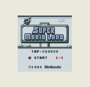
Images are the easiest to implement into sketch symbols, but they are rarely used. You may need to insert an image into a drawing if you have a screen with some type of animation on it. This can give the customer an idea of what they can see. Other areas of implementation could be artwork/designs or examples of it in its environment. To add an image, create a new sketch symbol and then insert an image.
Once you press on the “Image” button, define the size, and select an image from your machine to upload. After you put the image into the sketch, it can be resized as necessary. In this case, we put an image of the graphics that will be on our screen for our model.
Using these methods to utilize sketch symbols will enhance your drawings to provide an extra level of detail, which in turn will lead to better product quality. The biggest benefit is you now have higher quality drawings with less effort as sketch symbols are reusable by anyone once the sketch symbol library is shared.
Check out the recent Autodesk Virtual Academy on the topic covered within this blog post for an even deeper dive!
Sign up for KETIV’s weekly webinar, Autodesk Virtual Academy to see more updates for Autodesk manufacturing software!
Need assistance? Give us a call at 1-866-465-3848 or shoot us an email at support@ketiv.com and our team will be happy to help!