
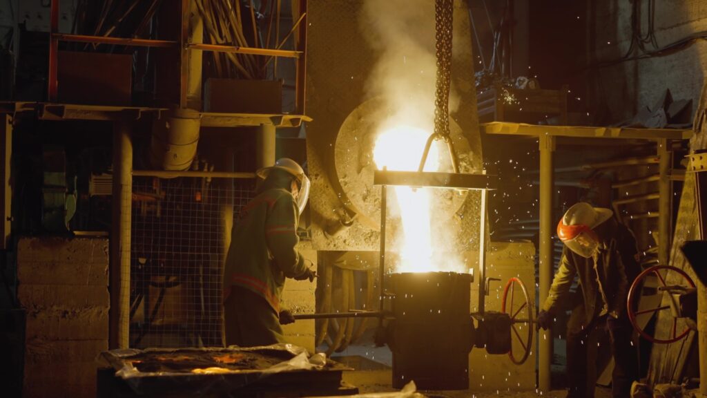
Sheet metal forming has traditionally been described as more art than science. The design of tooling, the stamping process, and the blank geometry have been refined through trial and error for decades.
That approach worked when margins were wide and timelines were long. It doesn’t work anymore.
What is sheet metal forming?
Sheet metal forming is a metal forming process used to turn a flat metal sheet into useful parts with a precise, repeatable shape. It sits at the intersection of sheet metal fabrication and metal fabrication, combining multiple forming techniques to control sheet thickness, bend radius, and final geometry. In a modern manufacturing process, engineers select the right sheet metal forming technique for the material, required strength, and complexity of the part. Whether the goal is simple brackets or complex shapes for structural components, sheet metal forming lets manufacturers turn raw sheet into durable metal components with consistent quality and shorter lead time. This forming process is the foundation for forming sheet metal into everything from housings and enclosures to safety‑critical sheet metal parts in vehicles and machinery.
How does sheet metal forming work?
Sheet metal forming works by using controlled forces and specialized tooling to reshape a flat metal sheet without removing material, relying on plastic deformation instead of machining. In a typical process, a flat metal sheet is positioned in the press brake or other forming equipment, then tooling applies force to create bends, curves, and complex shapes while managing bend radius and sheet thickness. Common sheet metal forming techniques include roll forming for long, uniform profiles, deep drawing and stretch forming for cups and complex contours, and cold forming or hot forming when extremely high strength or difficult materials are involved. Modern sheet metal fabrication also integrates processes like laser cutting and water jet cutting to cut the sheet to a near‑net shape before forming, improving material utilization and reducing downstream cutting. Atlas Manufacturing and other advanced manufacturers combine sheet metal bending, cutting, and forming in a single manufacturing process, using simulation and precision sheet metal fabrication methods to optimize material thickness, tooling, and forming sheet metal into consistent parts.
Those sheet metal forming fundamentals set the stage for why traditional trial‑and‑error doesn’t cut it anymore. Once you understand how many variables influence the forming process: material, thickness, tooling, forming technique, and part geometry, it becomes clear how quickly costs escalate when every improvement requires another physical tryout. That’s why the next step is looking closely at the real cost of physical tryouts and how they impact your timelines, scrap rates, and overall manufacturing profitability.
How simulation reduces defects and cost in sheet metal forming
The real cost of physical tryouts
The traditional process goes like this: build a tryout tool from less expensive materials, run test parts, measure what went wrong, modify the tool, repeat. Each cycle costs time and money. Each failed part is scrap.
Nissan documented a case where they had a tearing problem in a metal stamping operation. They built simulation models to determine the effect of blank edge radius on forming height. Based on simulation results, they designed a new die that solved the problem. Without simulation, that would have been weeks of physical iterations.
The defects you’re fighting are predictable: wrinkles from compressive buckling, cracks from excessive tensile stress, thinning in tight radii, and springback that throws parts out of tolerance. Each defect has physical causes. Those causes can be modeled.
The full scope of the challenge
Formability defects are the most visible problems, but the challenges in sheet metal forming go much deeper.
Tooling and die life directly affects your cost per part. Dies wear. Surfaces degrade. Understanding wear patterns, predicting when tools will need maintenance or replacement, and designing for longer life are all economic necessities.
Lubrication and friction modeling determines material flow. Too much friction and material tears. Too little and it wrinkles. Friction varies across the die surface, changes with temperature, and depends on lubricant type and application. Getting friction right in simulation means getting material flow right.
Thermal forming and hot stamping adds another layer of complexity. High-strength steels often require forming at elevated temperatures. Now you’re dealing with heat transfer between the blank and dies, temperature-dependent material properties, and thermal effects on springback. The physics gets harder, but so do the materials you can form.
Material behavior isn’t simple. Sheet metals are anisotropic; their properties differ depending on direction relative to the rolling direction. Strain rate matters, material behaves differently under fast and slow deformation. Accurate material models that capture anisotropy and rate dependence are essential for reliable predictions.
Press and system dynamics affect what actually happens on the shop floor. Press speed, cushion response, and slide motion profiles all influence forming outcomes. The forming process doesn’t happen in isolation; it happens in a machine with its own dynamic characteristics.
What’s actually happening in the die
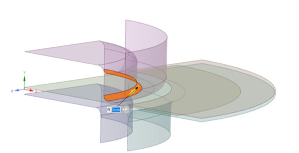
When sheet metal forms, it stretches, compresses, and flows in complex patterns determined by die geometry, blank shape, material properties, and process parameters like blankholder force and lubrication.
Wrinkles form when compressive stresses cause buckling. They’re often caused by low blankholder pressure that lets material slip. Draw beads can control this, but the location and shape of draw beads matters enormously.
Cracks form when tensile stresses exceed material limits. Small radii can block material flow, causing excessive thinning. Sometimes cracks result from excessive blankholder pressure that restricts flow. Sometimes they indicate that you’re trying to achieve too much deformation in a single stage.
Thinning beyond 20% of sheet thickness is a warning sign. Beyond 40%, you’ll likely see cracks. Simulation can map thinning across the entire part before you’ve pressed a single blank.
Springback happens because the material wants to return to its original shape after elastic stresses release. The amount of springback depends on material properties, forming geometry, and process history. It’s predictable, and compensation can be built into the die design].
What simulation reveals
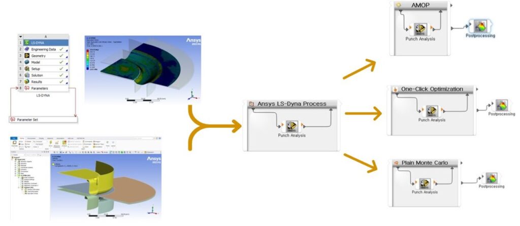
Modern forming simulation uses nonlinear finite element analysis to model the complete process. The software tracks material flow, predicts forming limit diagrams, calculates thinning distribution, and estimates springback.
More importantly, simulation lets you test alternatives quickly. Different blank shapes. Different blankholder pressures. Different draw bead configurations. Different material grades. Each iteration takes hours instead of days.
Engineers using simulation software report testing 10 to 40 different iterations of a design before physical tryout. That level of exploration would be impossible with physical prototypes.
Blank optimization alone can significantly reduce scrap. The goal is to design the initial blank, so the final formed part requires minimal trimming. Simulation can iterate on blank geometry, predict material flow, and optimize shapes for maximum material utilization.
The automotive case
The automotive industry adopted forming simulation years ago. Every major OEM and tier supplier uses it. Not because they’re technology enthusiasts, but because the economics are overwhelming.
But forming simulation in automotive isn’t just about making parts that don’t crack. The requirements go further:
Crash performance depends on how parts are formed. The forming process creates residual stresses and thickness variations that affect how a component behaves in a crash. Mapping forming results into crash simulation gives more accurate safety predictions.
Surface quality matters for visible panels. Subtle defects, slight waviness or orange peel effects, might pass forming limit checks but fail aesthetic standards. Part and process design can significantly affect the aesthetic quality of visible components, with defects emerging only during the first trials in the tryout stage of die manufacturing, when corrections are both time-consuming and costly.
Weight optimization drives material choices. Lightweighting means thinner gauges, higher-strength steels, aluminum, and mixed materials. Each change affects formability. Simulation lets you push material utilization closer to limits without crossing them.
Multi-stage processes require understanding cumulative effects. Progressive dies, transfer presses, and multi-step forming all involve material that’s been pre-worked. Each stage builds on the previous one, and problems compound.
Simulation doesn’t eliminate all problems. But it shifts discovery from the shop floor to the engineering office, where changes cost less, and timelines are more flexible.
The same logic applies to aerospace, appliances, medical devices, and any industry forming sheet metal. The physics doesn’t change. The economics favor virtual iteration over physical trial and error.
Getting started
At KETIV, we’ve worked with manufacturers on forming simulation for decades. Our team includes engineers who understand both the software and the shop floor realities.
Talk to a forming simulation expert: ketiv.com/ansys-consulting-services
Request an Ansys Discovery trial: ketiv.com/software/ansys/ansys-discovery
Join KETIV Virtual Academy: ketiv.com/ketiv-virtual-academy
See how other manufacturers approach these challenges: ketiv.com/customer-stories
Explore Ansys LS-DYNA and Forming capabilities: ketiv.com/ansys-software/structural-simulation-software