
It’s the day you’ve been waiting for: you’re going to buy a new car. On the lot, you eye different models. You already know the performance specs you want, so right now you’re all about style. When it comes to the look of the vehicles, a certain curve and flow is appealing, while the look of an ungainly bumper or outdated side panel can kill your interest completely.
In other words – looks matter. An attractive product appearance can command a high price tag, while just one off-putting aspect can cost the dealership a sale. That’s why some automotive manufacturers are using CFD (Computational Fluid Dynamics) Modeling to perfect components. Solutions like Moldflow offer simulation modeling, fluid simulation, simulation modeling, injection CFD modeling, and other tools to ensure a high aesthetic result. From shrinkage to warpage to sink marks, CFD modeling helps manufacturers test a variety of impacts to achieve the vehicle design they want – and do so in a timely, cost-effective way.
Let’s break down the benefits and methods of CFD modeling for vehicle design.
Using CFD Modeling for Part Shrinkage Prediction
Shrinkage influences how a molded part deflects, so you’ll use similar simulation modeling approaches for both minimizing unnecessary shrinkage and addressing part warpage. You have a few options here. Moldflow simulations can analyze shrinkage through the warpage analysis; however, you can obtain more detailed result plots when you enable a feature called “Isolate Cause of Warpage” before running the analysis. That includes results called “Deflection, Differences in Shrinkage.” You’ll learn the amount of part deflection due to shrinkage variations, as well as volumetric shrinkage, shrinkage compensation values, and even the fill result. By simulating the free flow of fluid and its interaction with surfaces, CFD (computational fluid dynamics) will track flow orientation and identify where more shrinkage may occur.

Mold designers usually apply rule-of-thumb values for shrinkage based on material properties, which means simulation can help you catch excess or unexpected shrinkage when designing molds. You can use Moldflow simulation to make other steel-safe recommendations to tool designers, or provide insights for reducing shrinkage when your targeted areas aren’t within tolerance.
Here are a few ways you can proceed in that situation:
- Modify process settings. Experiment with ranges of process settings, such as hold time/pressure or melt/mold temperatures, to see if you can process it out rather than resort to more dramatic changes such as mold changes. Be aware that some process modifications could lead to an increase in internal stresses, such as freezing the material with a colder mold to stop shrinkage.
- Explore gating options. If flow direction is causing the shrinkage, adding gates or relocating gates may reduce areas with excess shrinkage. This will partly depend on part geometry and gating restrictions, so use CFD Running Flow simulations to identify if this is an option.
- Identify high-shear regions. Increased orientation means Moldflow shear results can coincide with high-shrink areas. One way to minimize shearing in those regions? Add rounds/fillets, flow directors, or other part features.
- Modify part geometry for uniform thickness. If you see different shrinkage rates, it could be due to variations in part wall thickness. Simulation can help you see if you need to adjust wall thickness, or if processing changes are the answer. That might include increasing hold time/pressure or adjusting mold or melt temperatures. Luckily, the Moldflow parametric analysis gives you a range of specified thicknesses so you can find the best option based on quality criteria.
Using CFD modeling for Part Warpage Prediction
Moldflow’s default warpage result plots can show you useful trends, no doubt. But to really see the entire deflection story, you’ll want to use additional result plots to resolve the out-of-tolerance warpage.
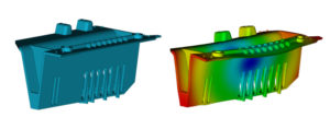
The good news is that Moldflow Insight can address all three causes of part warpage. Just as you did with shrinkage, you’ll want to enable the advanced warpage result plots before running a Warp analysis by selecting the “Isolate Cause of Warpage” option. After your simulation is complete, you can review the result plots for warpage caused by (a) “Differential Shrinkage” (b) “Differential Cooling” or (c) “Orientation Effects.”
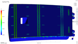
Default result plots such as Volumetric Shrinkage and Part Temperature plots can also help you understand why warpage is happening. Once you’ve identified and solved the issue, be sure to repeat the deflection analysis to evaluate how well your changes mitigated other warpage plots.
Using CFD modeling for Sink Mark Evaluation
Moldflow’s sink mark result does exactly what it promises: helps you understand the probability and depth of a sink mark occurring. Using built-in sink-mark results like Sink Mark Estimate, Sink Mark Index, or Sink Mark Depth can help you predict the behavior of the material opposite a part feature. True, some areas like thick regions and non-rib-related areas won’t be captured through those built-in results. But other Moldflow results can still guide you through potentially difficult areas, like using the Volumetric Shrinkage result to foresee voids or sink marks through shrinkage differences.
Some sink marks are due to insufficient packing – and Moldflow can help with that too if you optimize packing profiles. Conduct a virtual design of experiments (DOE) study with sink marks as a quality criteria factor; include melt and mold temperatures too. The DOE will tell you if packing pressure can resolve the issue.
If it can’t, you may need more expensive tooling modifications. But before you do that, try simulating the following options with Moldflow Insight:
- Increase runner or gate size: If the gate freezes early and can’t stay open long enough to pack the part, try increasing the size of the gate or runners and review it in the simulation.
- Move the gate: Gates should be arranged from thick to thin. If the area with sink marks is thicker than the surrounding regions, try relocating the gate. Just use simulation first, as this is a more extreme tool modification and leads to several days or even weeks delay in your production cycle.
- Use alternate material: Changing to a new material can put more tool work on your plate – but alternate material could also provide wider processing windows and different flow patterns. Testing this in simulation will help you confirm if the existing tool geometry will work for the new material or if you’ll have to make changes to the cavities, runners, and gates. Even different grades of the same material can perform differently.
- Modify parts: One trick for getting difficult areas to pack better is reducing thick regions. Set up multiple simulations through a parametric study or Design of Experiments (DOE) within Moldflow Insight to compare visually with one another. You’ll get insights like how thick a rib can be to produce a sink mark; at the same time, you can use process settings to identify the correct ranges the mold must be run at to achieve those.
Turning Simulated Perfection into Product Success
Designing the perfect product is never easy. The interplay of materials offers too many possibilities for error. But tools like CFD modeling can save you budget and frustration by letting you test, experiment, and validate as often as you need to. With greater freedom to refine the design and stave off failure, your automotive design teams will have renewed ability to innovate and explore – and exceed even your best hopes for your products.