
What is the easiest way to create a simple cam in Inventor? Your first response might be: “Just create a sketch outline of the cam using the Spline function and then extrude.” It makes sense right? The problem with the Spline method however, is it has a tendency to not create one continuous smooth edge and create a break in the face of the edge. This can lead to the follower not behaving correctly.
A better solution is the Disc Cam Generator which creates a fully functioning cam for you in the assembly model along with a separate part file for the cam.
Time to dive into how this tool works. You can find the Disc Cam generator by going to Design Tab > Power Transmission > Disc Cam.

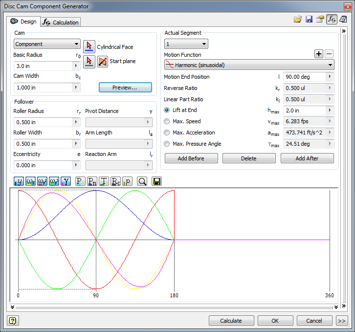
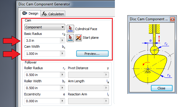
Let’s start in the “Cam” section of the dialog box. Here we can set the parameters for the cam itself: Start Plane, Basic Radius (ro), and Cam Width (bc).
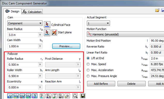
The next section pertains to the Follower where we input information such as Roller Radius (rr), Eccentricity (e), and the Roller Width (br). There are others as well, but for our basic cam we’ll only need the Roller Radius and Width.
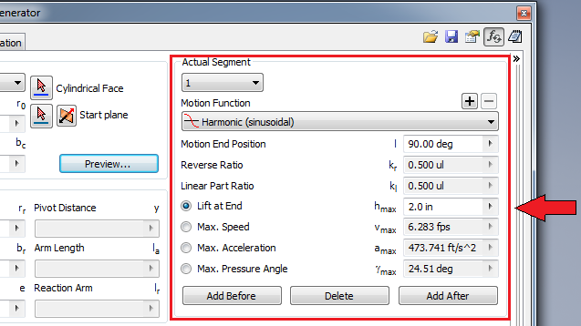
Finally, we’ll need to fill out the fields under Actual Segment. Here the user can set variables such as: length of the Lift at End, the Max Speed, Max Acceleration, and Max Pressure Angle. In this example I’ve only changed the Lift at End. Once we set the value for one, the data for the others will update accordingly.
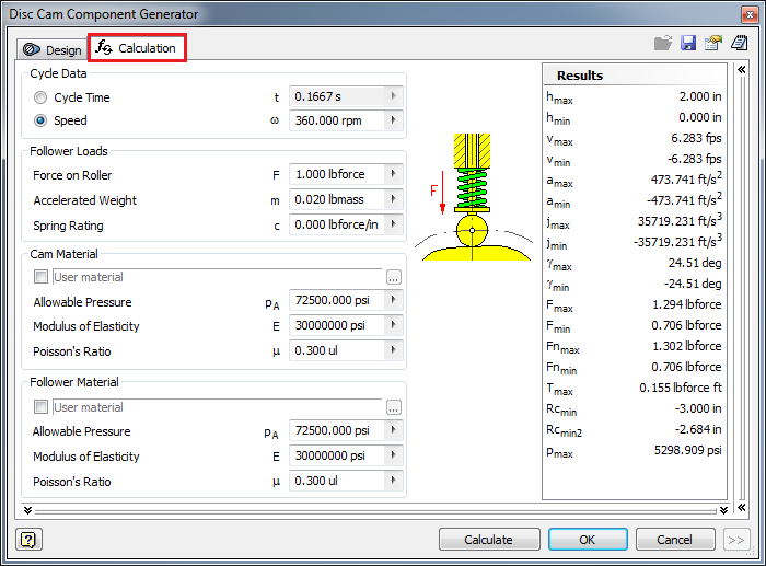
For users who want to see more advanced settings, take a look at the Calculation tab. In my example cam I haven’t set any of these values, but here you can set even more options to customize the cam to your specifications.
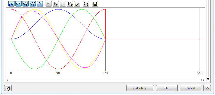
Now that we have input all the necessary information, take a look at the bottom of the window and you’ll see a graph. All the data and information from above is calculated and shown here. This graph also evolves and adapts to changes made to the information above. We can actually see this change by clicking “Calculate” at the bottom. It shows Lift, Acceleration, Speed, Pressure Angle, Torque, Normal Force and others as well.
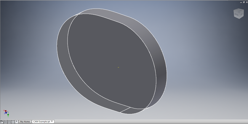
Now that we have input all the necessary data, all that’s left is to click “Calculate” and then “OK” and the program will generate the cam for us. Below is the cam that was generated. Now it’s your turn to create one!
Interested in learning more about Inventor?
We teach Inventor Essentials training courses every month.
Sign up today!
Great post Bryce.